5 Tips for a Fully Electrical Heating Pyrolysis System?

Time:2026-09-21 Author:Isabella
0%

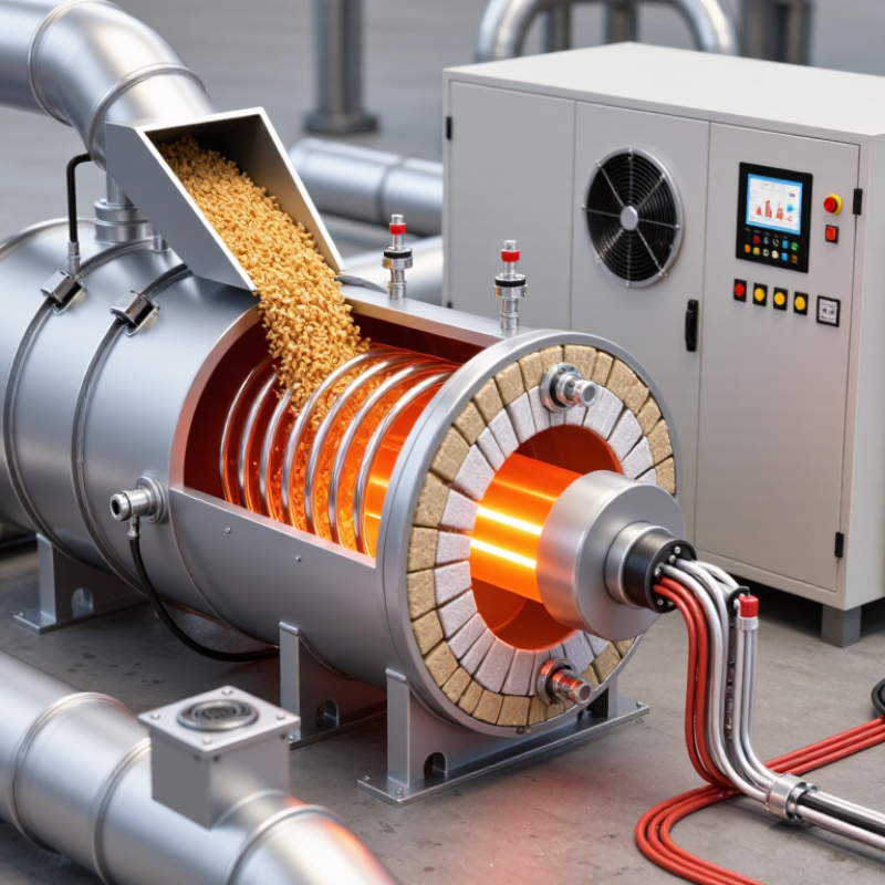
Designing a reliable Fully Electrical Heating Pyrolysis System requires more than replacing burners with electric heaters. It demands careful control of heat transfer, feedstock preparation, insulation, and operating safety. This guide presents five practical tips for improving system performance, energy efficiency, and day-to-day reliability. Each tip reflects common engineering concerns found during equipment selection, commissioning, and routine operation. Small details matter. A loose sensor connection can distort temperature readings and affect the entire process.

The discussion covers heater sizing, temperature uniformity, electrical load planning, thermal insulation, and automated monitoring. It also considers moisture content, particle size, and material feeding consistency, because unstable input conditions can produce unstable results. Qualified engineers should verify electrical protection, grounding, ventilation, emergency shutdowns, and applicable local requirements before operation. Manufacturer specifications and documented testing should support every major decision. However, no design is perfect. A clean simulation may fail when dust builds around a heater or when production demand changes suddenly. Real operating data must challenge the original assumptions. Operators should record temperatures, power consumption, maintenance findings, and unusual odors during controlled inspections. These records can reveal problems before they become expensive failures. The goal is not merely higher output. It is a safer, more predictable, and easier-to-maintain pyrolysis process. That takes patience.
5 Tips for a Fully Electrical Heating Pyrolysis System?

Define the Core Design of a Fully Electric Pyrolysis System

5 Tips for a Fully Electrical Heating Pyrolysis System

Define the Core Design of a Fully Electric Pyrolysis System

A fully electric pyrolysis system begins with its energy boundary. Define feedstock moisture, particle size, throughput, and target temperature before selecting heaters. The reactor should provide even heat transfer, stable residence time, and minimal oxygen intrusion. Direct resistance heating can respond quickly, while induction or radiant heating may suit specific reactor materials. Each option has limits.

The electrical architecture needs more than heating elements. Include a transformer, variable-frequency drives, temperature sensors, power meters, and an emergency shutdown circuit. Insulation must reduce heat loss around the reactor shell, pipework, and gas treatment section. The International Energy Agency reports that industry consumes roughly 40% of global final energy. This makes every recovered kilowatt important. A small heat leak becomes expensive.

Control quality decides daily performance. Use several temperature zones instead of one sensor near the outlet. Connect feed-rate control with heater output and vapor pressure. The IPCC Sixth Assessment Report stresses that electricity emissions depend strongly on generation sources. Therefore, record electricity intensity per tonne of feedstock. Renewable power can improve results, but only after grid conditions and backup power are measured. IRENA’s Renewable Power Generation Costs in 2023 reported that 81% of newly commissioned utility-scale renewable projects were cheaper than fossil alternatives. The figure supports electrification, not careless design. Real systems still face unstable loads, fouling, and imperfect insulation. Those problems deserve testing before commercial scaling.

Select Electric Heating Methods and Size the Main Components

A fully electrical pyrolysis system begins with the heating method, not the heater catalogue. Resistance heating suits compact reactors and offers simple control. Induction can heat metallic reactor walls quickly, but insulation and material compatibility need careful review. Dielectric heating may improve internal heating for selected feedstocks, yet moisture changes can reduce stability. IEA Bioenergy Task 34 places fast pyrolysis commonly around 450–550°C, depending on feedstock and residence time.

Size the main components from measured duty. Include feed heating, moisture evaporation, reaction heat, wall losses, and gas-treatment loads. For example, 1,000 kilograms of feed containing 15% moisture carries about 150 kilograms of water. That water alone requires substantial energy before pyrolysis begins. Add temperature ramping and heat-up time. Cold spots matter. A practical first estimate may include a 15–25% design margin, but pilot measurements should replace that assumption.

The power supply must handle continuous load, startup demand, and heater zoning. A 500-kilowatt process load does not automatically require a 500-kilowatt electrical connection. Controls, transformers, cables, and cooling systems also consume capacity. The U.S. Department of Energy’s Industrial Decarbonization Roadmap identifies process heating as roughly half of manufacturing energy use, highlighting the value of efficient controls. Still, electric efficiency can disappoint when insulation is thin or doors leak heat. I would test each zone with thermocouples, verify surface temperatures, and review real operating data before final sizing.

Example Electrical Heating Load for a Pyrolysis System

This illustrative sizing case assumes a continuous feed rate of 1,000 kg/h, 10% moisture, heating from 25°C to 500°C, an average solid heat capacity of 2.0 kJ/kg·K, 300 kJ/kg reaction heat, and a 20% allowance for heat losses. The calculated process duty is approximately 392 kW, while the recommended installed electric-heater capacity is approximately 471 kW.

Resistive heating is generally suitable for indirect reactor heating because it is simple to control and scale. Induction heating requires a suitable conductive susceptor, while infrared heating is most effective where direct line-of-sight radiation is available. Final heater, cable, switchgear, and cooling-system sizes must be verified against the reactor geometry, insulation performance, feed composition, and local electrical code.

Control Feedstock Preparation, Feeding, and Pyrolysis Conditions

5 Tips for a Fully Electrical Heating Pyrolysis System

Control begins before the reactor. The World Bank reports 2.01 billion tonnes of municipal waste generated globally each year. Feedstock is rarely uniform. Remove stones, metals, and oversized fibers before drying. A practical target is 10–15% moisture. Wet material consumes valuable electrical energy during evaporation. Screen particles into a narrow size range. Around 5–20 millimeters often supports steadier feeding and heat transfer, although each reactor needs testing.

Use a sealed hopper, a controlled screw feeder, and load-cell monitoring. Avoid sudden surges. They can cool the reactor and create uneven vapors. Keep bridging under control with gentle agitation, not excessive vibration. Electrical heaters respond quickly, but cold feedstock can still cause sharp temperature drops. Install thermocouples near the wall, centerline, and outlet. Measure oxygen continuously. Small leaks matter. The IEA Bioenergy Task 34 identifies approximately 350–650°C as a common range for slow pyrolysis. Select the setpoint according to feedstock and product targets.

Maintain stable residence time, airflow isolation, and pressure. Use staged heating rather than one aggressive power increase. Record moisture, particle size, feeder speed, temperature, and product yield for every batch. World Bank waste data highlights the scale of feedstock variability, but it does not solve plant-level inconsistency. Our own process assumptions may be wrong. Recheck them with moisture tests and trial runs. A perfect recipe is unlikely. Variability is the real operating condition.

Integrate Energy Management, Gas Handling, and Emission Controls

A fully electrical heating pyrolysis system succeeds when power, gas flow, and emissions are designed as one operating loop. Map the energy balance before selecting heaters. Measure feed moisture, reactor losses, insulation performance, and peak demand. Variable power controls can reduce electrical spikes, but they need stable temperature feedback. Keep separate meters for heaters, motors, and auxiliary equipment. This makes abnormal consumption visible. Small detail. Large consequences.

Gas handling needs equal attention. Use staged condensation or filtration suited to expected vapors, then monitor pressure, temperature, and flow continuously. Relief devices, leak detection, and controlled vent routing should remain accessible during inspection. An inert purge may protect equipment during shutdown, but its volume must be calculated carefully. Too much purge gas can overload treatment equipment. Too little can leave uncertainty. Operators should log trends, not only alarms, because a slow pressure rise often appears before a serious fault.

Emission controls should match measured gas composition, not assumptions from a design sheet. Sampling points before and after treatment help verify removal performance. Thermal oxidizers, scrubbers, or particulate filters may be suitable, depending on the process and local requirements. Calibration records and independent engineering reviews strengthen decisions when readings conflict. One practical weakness is overconfidence in simulations. Real feedstock varies. Pilot data deserves more weight.

5 Tips for a Fully Electrical Heating Pyrolysis System? – Integrate Energy Management, Gas Handling, and Emission Controls
Tip Primary Objective Recommended Design and Operating Measures Indicative Technical Data Key Performance Indicators Expected Benefit
1. Match Electrical Heating to the Process Temperature Profile Provide stable, controllable heat while avoiding unnecessary electrical demand. Use independently controlled heating zones, thermocouples at multiple process locations, insulated reactor walls, and ramp-rate limits. Apply feed-forward control based on feed rate and moisture, combined with feedback control from reactor temperature. Typical pyrolysis temperatures are approximately 400–700 °C, depending on feedstock and product targets. Heating demand increases significantly with feed moisture because water must be heated and vaporized. Temperature deviation: typically maintained within approximately ±5–10 °C after stabilization; specific electricity consumption reported as kWh per tonne of feed. More consistent product quality, lower heat loss, and reduced peak electrical load.
2. Integrate Energy Management and Heat Recovery Reduce net electricity consumption and improve overall thermal efficiency. Install power meters for each heating zone, variable-speed drives for fans and pumps, automatic demand scheduling, and high-temperature insulation. Recover sensible heat from hot product, exhaust gas, or non-condensable gas cooling streams where safe and practical. Monitor real-time power factor, heating power, feed throughput, reactor temperature, and recovered-heat duty. Heat recovery should be designed around the actual temperature and composition of each stream. Specific energy consumption: kWh/t; peak demand: kW; heat-recovery rate: %; electrical efficiency: %. Lower operating cost, reduced grid demand, and improved utilization of process energy.
3. Separate, Cool, and Safely Manage Pyrolysis Gas Control combustible gas, condensable vapors, pressure, and product recovery. Use staged vapor cooling or condensation, knock-out vessels, demisters, pressure control, non-return protection, gas-flow measurement, and appropriately sized relief devices. Keep air ingress out of the reactor and provide a controlled flare or thermal oxidizer for off-specification gas. Non-condensable gas commonly contains variable proportions of H₂, CO, CO₂, CH₄, and light hydrocarbons. Gas composition depends strongly on feedstock, temperature, residence time, and reactor configuration. Reactor pressure stability; gas flow in Nm³/h; oxygen concentration in protected zones; condensate recovery in kg/t; flare or oxidizer availability. Improved safety, higher recovery of condensable products, and fewer uncontrolled releases.
4. Design Emission Controls Around Actual Pollutants Control particulate matter, carbon monoxide, volatile organic compounds, acid gases, and nitrogen oxides as applicable. Use staged combustion or a thermal oxidizer for combustible vapors when required. Combine particulate control, such as a cyclone or suitable filter, with activated carbon, wet scrubbing, or other treatment selected from measured gas composition. Avoid treating emissions with a single control device when multiple pollutants are present. Emission-control selection should consider PM, CO, VOCs, NOₓ, SOₓ, HCl, and odor compounds. Required limits are determined by local permits, feedstock, operating mode, and stack-testing requirements. Stack concentrations in mg/Nm³; CO and VOC destruction efficiency; particulate concentration; pressure drop; scrubber pH or reagent usage where applicable. Better regulatory compliance, lower odor impact, and more predictable operation.
5. Add Interlocks, Monitoring, and Preventive Maintenance Prevent unsafe conditions and maintain long-term electrical and gas-system performance. Interlock heaters with minimum gas flow, acceptable oxygen concentration, pressure limits, cooling-water availability, and emergency shutdown status. Continuously monitor temperature, pressure, flow, oxygen, carbon monoxide, and combustible-gas levels in relevant areas. Use independent high-temperature and high-pressure trips, alarm history, calibration schedules, grounding and bonding checks, leak testing, filter inspection, and periodic verification of relief and shutdown devices. Unplanned downtime; alarm frequency; sensor availability; maintenance completion rate; safety-trip response time; gas-leak incidents; control-loop performance. Higher availability, safer operation, fewer process interruptions, and more reliable emissions performance.
Note: Indicative values are general engineering ranges or measurement categories, not universal design limits. Final operating conditions, electrical ratings, gas-treatment equipment, and emission limits must be established through feedstock testing, process hazard analysis, equipment design calculations, and applicable local regulations.

Improve Safety, Automation, Maintenance, and Overall System Efficiency

5 Tips for a Fully Electrical Heating Pyrolysis System

Safety begins with disciplined heat control. Divide the reactor into independent heating zones, then monitor each zone with separate temperature sensors. Add high-temperature cutoffs, pressure relief devices, grounding, and accessible emergency stops. Interlocks should prevent heating when the reactor door is open or cooling flow is unavailable. Keep electrical cabinets dry, clean, and clearly labeled. Small oversights can become serious faults.

Automation improves consistency and reduces operator exposure. Use a control system that records temperature, pressure, power use, and alarm history. Set gradual heating rates instead of relying on sudden power changes. A live trend screen can reveal unstable zones before material quality changes. Use tested sensors, not assumptions. I once underestimated sensor drift during long operation; that mistake made the data look more reliable than it was.

Maintenance protects efficiency. Inspect heating elements, cable connections, insulation, seals, and cooling lines on a fixed schedule. Remove dust from electrical panels and check for loose terminals. Measure energy consumption per operating cycle, then compare it with output quality. Better insulation often saves more power than simply increasing heater capacity. Keep spare sensors and fuses available. Document every adjustment, even the unsuccessful ones. That record supports safer decisions and helps technicians identify recurring problems. Efficiency is not only faster heating. It is stable heating, lower heat loss, fewer shutdowns, and predictable maintenance.

FAQS

Which electric heating method suits a compact pyrolysis reactor?

Resistance heating offers simple control and fits compact reactors. Cold spots still matter. Test temperature uniformity before final selection.

When can induction heating be useful?

Induction can heat metallic reactor walls quickly. Check insulation, wall materials, and compatibility first. Fast heating is not automatically efficient.

Can dielectric heating improve pyrolysis performance?

It may improve internal heating for selected feedstocks. Changing moisture can reduce stability. Pilot testing is necessary.

How should the main electrical load be estimated?

Include feed heating, moisture evaporation, reaction heat, wall losses, and gas-treatment loads. Add temperature ramping and heat-up time. A 15–25% margin may help initially, but measurements should replace assumptions.

Why does feedstock moisture require close control?

Water consumes electrical energy before pyrolysis begins. For example, 1,000 kilograms of feed at 15% moisture contains 150 kilograms of water. A practical moisture target is often 10–15%.

What feed preparation supports steadier operation?

Remove stones, metals, and oversized fibers before drying. Screen particles into a narrow range, often about 5–20 millimeters. Each reactor still needs testing.

How can feeding problems be reduced?

Use a sealed hopper, controlled screw feeder, and load-cell monitoring. Avoid sudden surges. Gentle agitation can reduce bridging without excessive vibration.

Which measurements should operators record?

Record moisture, particle size, feeder speed, temperatures, residence time, and product yield. Place thermocouples near the wall, centerline, and outlet. Measure oxygen continuously. Our assumptions may be wrong.

How should heating and reactor conditions be controlled?

Use staged heating instead of one aggressive power increase. Maintain stable residence time, airflow isolation, and pressure. Check for small leaks. A perfect recipe is unlikely.

Conclusion

A Fully Electrical Heating Pyrolysis System is designed around precise electric heat generation, controlled reactor temperature, and stable material flow. The process begins by selecting an appropriate heating method and correctly sizing heaters, reactors, insulation, sensors, and power equipment. Feedstock should be properly sorted, dried, and prepared to maintain consistent feeding and predictable pyrolysis conditions. Careful control of temperature, residence time, pressure, and feed rate helps improve product quality while reducing unnecessary energy use.

Effective system integration is equally important. Energy management should balance electrical demand, recover usable heat where practical, and minimize operating losses. Gas handling equipment must safely collect, cool, filter, and monitor process gases, while suitable emission controls support responsible operation and regulatory compliance. Finally, strong automation, emergency protection, routine inspection, and accessible maintenance design can improve reliability and worker safety. By coordinating these elements, the system can achieve stable performance, efficient energy utilization, lower environmental impact, and long-term operating efficiency.


Isabella

Isabella

Isabella is a dedicated marketing professional with a sharp focus on driving brand growth and engagement through strategic content creation. With an extensive background in digital marketing, she combines her passion for storytelling with her keen understanding of industry trends to deliver......